info@jpsgy.com

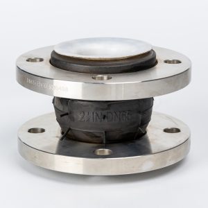

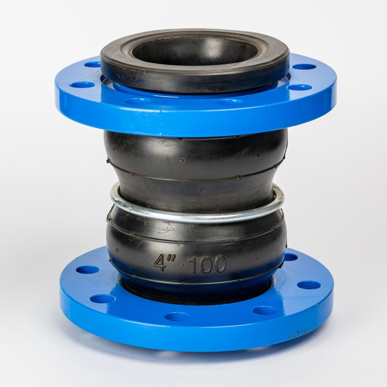
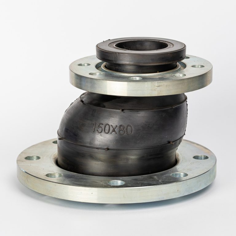
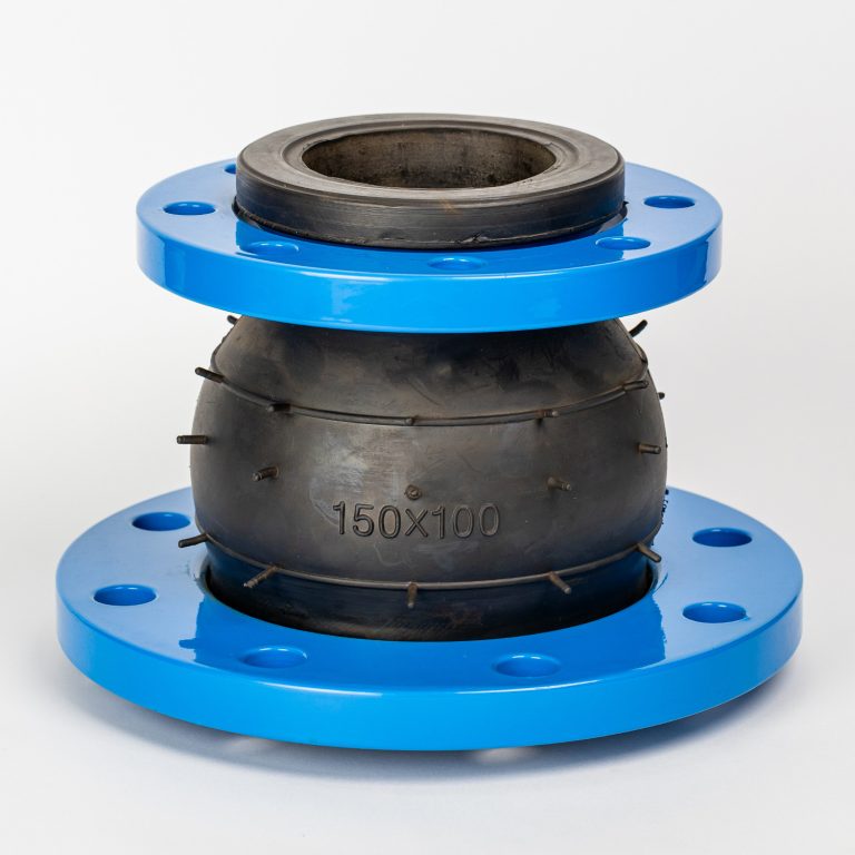
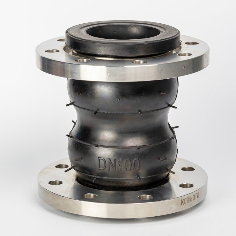
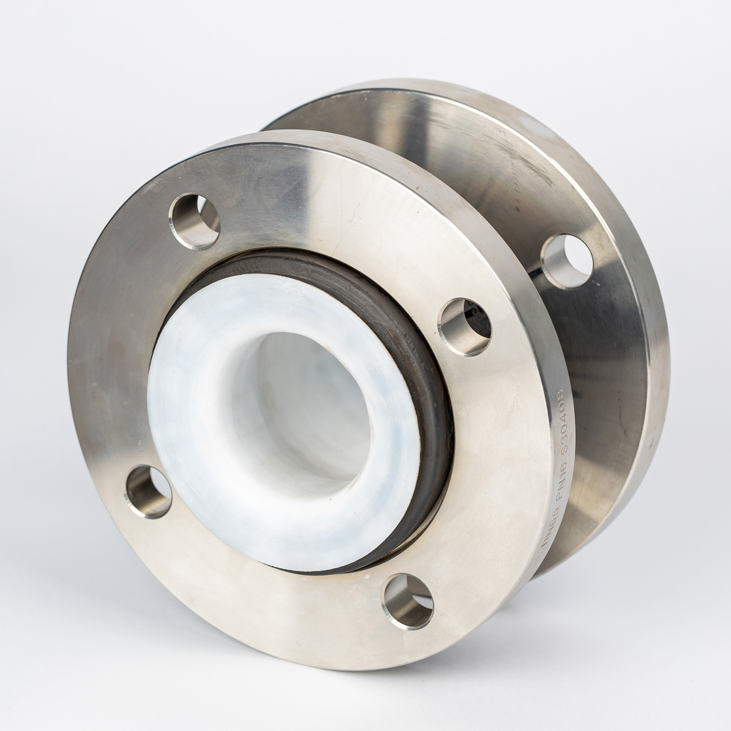
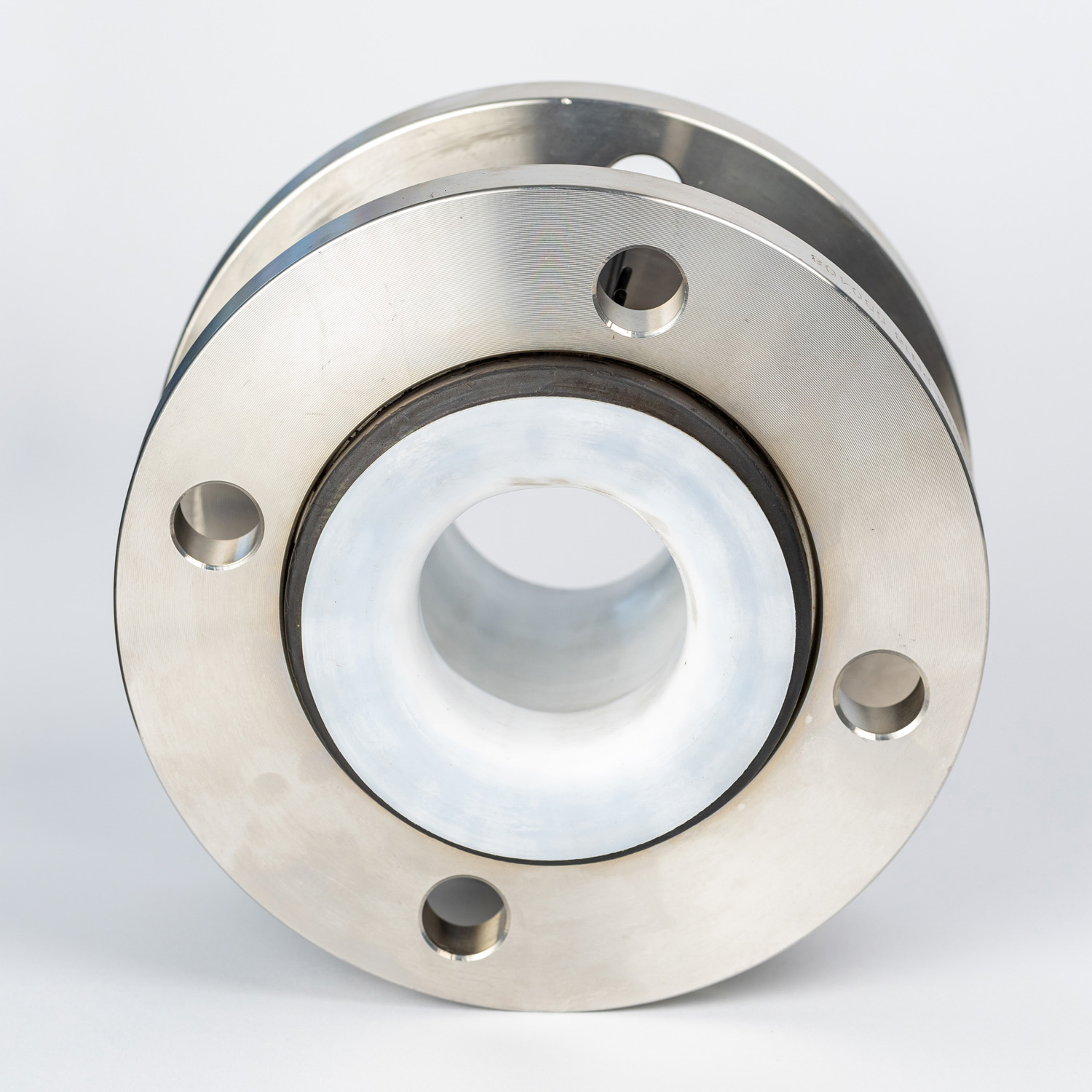
단일 구형 스테인리스 스틸 플랜지 유연한 PTFE 라이닝 NBR 또는 EPDM 고무 확장 조인트
사이즈
DN25 ~ DN3000
압력
PN6~PN40
온도
-15 ~ 80℃
플랜지 표준
DIN, ANSI, JIS 등
플랜지의 재질
스테인리스 스틸 304, 316, 321 등
고무의 재질
NR, NBR, CR, EPDM, PTFE 등

개요
PTFE는 기존 고무 튜브 팽창 조인트에 비해 부식성 화학물질 및 온도에 대한 내성이 뛰어납니다. 금속 팽창 조인트에 비해 소음 전달 및 감쇠 효과가 낮을 뿐만 아니라, 이종 금속 접합 시 전기 분해 발생 가능성도 줄어듭니다. 팽창 조인트는 단일 개방형 와이드 아치 디자인의 고무 스풀 타입이어야 합니다. 조인트 구조는 EPDM 튜브와 일체형 PTFE 라이너가 있는 커버로 구성되어야 합니다. 조인트는 시스템의 설계 압력 및 온도를 충족하도록 설계되어야 합니다.
팽창 조인트 끝단은 150# 등급 표준으로 드릴링된 플랜지여야 하며, 전체가 고무로 마감되어 본체와 일체형이어야 합니다. 아연 도금 탄소강으로 제작된 분할 플랜지 백킹 링이 제공되어야 합니다.
팽창 조인트는 필요에 따라 배관 시스템 및 장비의 움직임과 진동을 견딜 수 있어야 합니다.
압력 추력으로 인한 팽창 조인트의 과도한 신장을 방지하기 위해 아연 도금 탄소강으로 제작된 타이로드가 있는 제어 장치를 포함해야 합니다. 제어봉의 수와 크기는 최대 시스템 시험 압력에 충분해야 합니다.
사양
| No. | Part | Material | ||||
| 1 | Body | (NR)、(CR)、(IIR)、(NBR)、(FKM)、(EPDM) | ||||
| 2 | Inner & Outer Rubber | (NR) (CR)(IIR) (NBR)(FKM)(EPDM)(PTFE) | ||||
| 3 | Body Carcass | Nylon cord fabric | ||||
| 4 | Reinforcing Ring | Multi-strand coppering steel wire | ||||
| 5 | Flange | Cast and forged carbon steel(Q235)、Stainless steel(201、304、316、321)、Plastic(CPVC、PVDF、PPH、UPVC、RPP) | ||||
기술적 매개변수
| Item |Medol | KXT-1 | KXT-2 | KXT-3 | 1. If media is oil, acid or alkali. 2. If special requirements for working temperature 3. If OEM orders with drawings or samples 4. Please Inform us about above when ordering |
| MpaWoring pressure | 1.0(10) | 1.6(16) | 2.5(25) | |
| Mpa Burst Pressure | 2.0(20) | 3.0(30) | 4.5(45) | |
| Kpa Vacuum | 53.3(400) | 86.7(650) | 100(750) | |
| Applicable Temperature | -20℃~+115℃(-30℃~+250℃)-20℃~+115℃(-30℃~+250℃ under special conditions) | |||
| Applicable Medium | Air, compressed air, water, sea water, oil, acid, alkali, etc. | |||
| Note: the materials of main parts are the same with those of KXT type | ||||
| DN Nominal Diameter (mm) | Axial displacement(mm) | Length(mm) | Haorizontal isplacement (mm) | Angular deflection(a1+a2)° | ||
| mm | inch | elongation | compression | |||
| 32 | 1.25 | 6 | 9 | 95 | 9 | 15° |
| 40 | 1.5 | 6 | 10 | 95 | 9 | 15° |
| 50 | 2 | 7 | 10 | 105 | 10 | 15° |
| 65 | 2.5 | 7 | 13 | 115 | 11 | 15° |
| 80 | 3 | 8 | 15 | 135 | 12 | 15° |
| 100 | 4 | 10 | 19 | 150 | 13 | 15° |
| 125 | 5 | 12 | 19 | 165 | 13 | 15° |
| 150 | 6 | 12 | 20 | 180 | 14 | 15° |
| 200 | 8 | 16 | 25 | 210 | 22 | 15° |
| 250 | 10 | 16 | 25 | 230 | 22 | 15° |
| 300 | 12 | 16 | 25 | 245 | 22 | 15° |
| 350 | 14 | 16 | 25 | 255 | 22 | 15° |
| 400 | 16 | 16 | 25 | 255 | 22 | 15° |
| 450 | 18 | 16 | 25 | 255 | 22 | 15° |
| 500 | 20 | 16 | 25 | 255 | 22 | 15° |
| 600 | 24 | 16 | 25 | 260 | 22 | 15° |
| 700 | 28 | 16 | 25 | 260 | 22 | 15° |
| 800 | 32 | 16 | 25 | 260 | 22 | 15° |
| 900 | 36 | 16 | 25 | 260 | 22 | 15° |
| 1000 | 40 | 18 | 26 | 260 | 24 | 15° |
| 1200 | 48 | 18 | 26 | 260 | 24 | 15° |
| 1400 | 56 | 20 | 28 | 350 | 26 | 15° |
| 1600 | 64 | 25 | 35 | 350 | 30 | 10° |
| 1800 | 72 | 25 | 35 | 350 | 30 | 10° |
| 2000 | 80 | 25 | 35 | 350 | 30 | 10° |
| 2200 | 88 | 25 | 35 | 400 | 30 | 10° |
| 2400 | 96 | 25 | 35 | 400 | 30 | 10° |
| 2600 | 104 | 25 | 35 | 400 | 30 | 10° |
| 2800 | 112 | 25 | 35 | 400 | 30 | 10° |
| 3000 | 120 | 25 | 35 | 400 | 30 | 10° |
| Note: 1. Special requirements can be made according to user drawings. The sphere can be made of nitrile rubber, EPDM, chloroprene rubber and other materials. 2. For suspended water supply, use products above DN200. The pipeline must have a fixed support or fixed bracket, otherwise the product should be installed with an anti-pull-off device. 3. If the user uses a rubber joint, the corresponding flange should be a valve flange. | ||||||