info@jpsgy.com

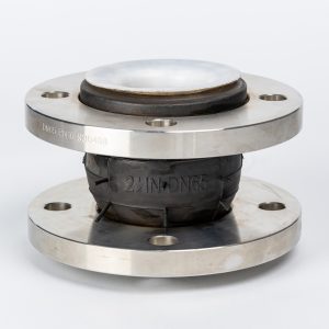

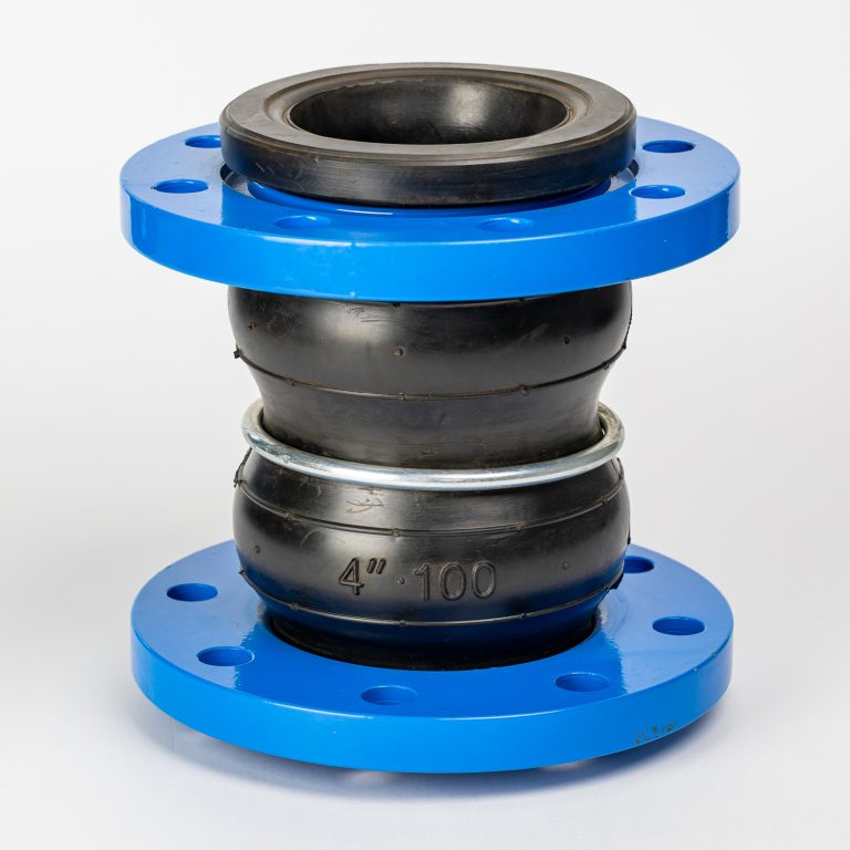
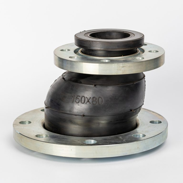
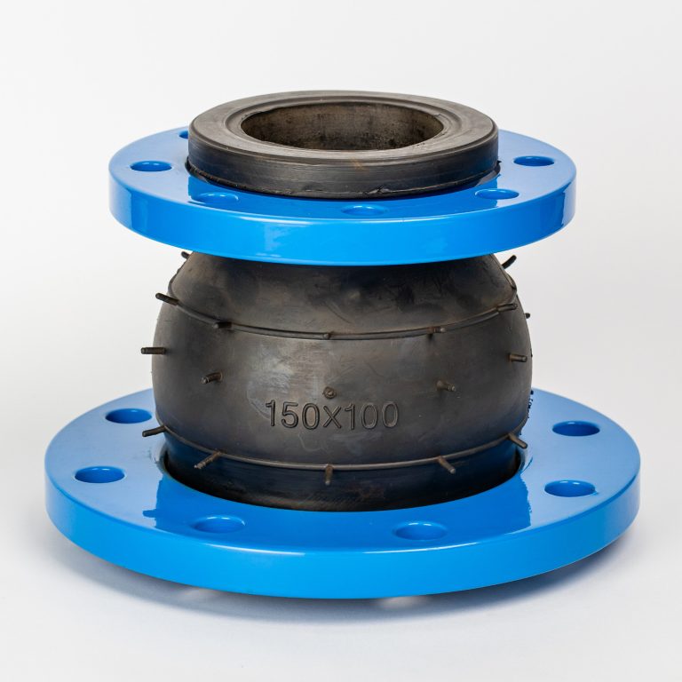
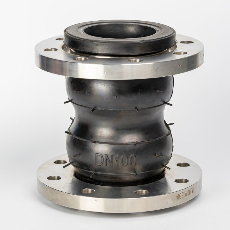
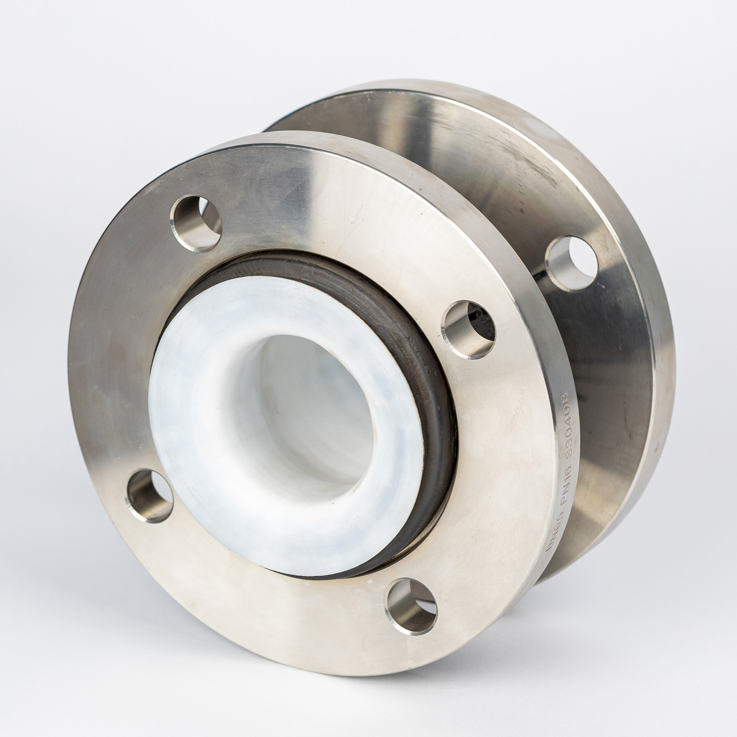
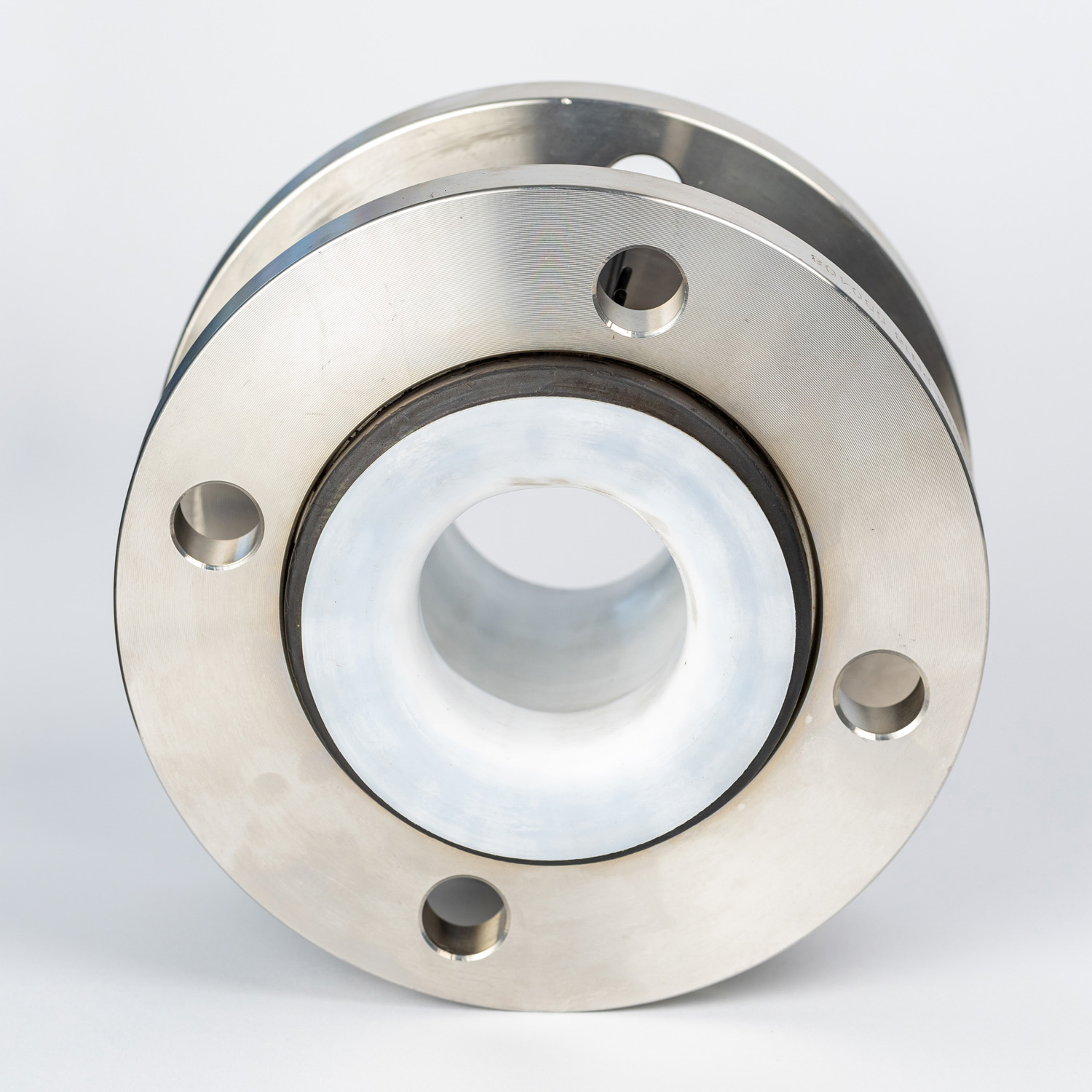
単球ステンレス鋼フランジ付きフレキシブルPTFEライニングNBRまたはEPDMゴム伸縮継手
サイズ
DN25 ~ DN3000
プレッシャー
PN6~PN40
温度
-15 ~ 80℃
フランジ規格
DIN、ANSI、JISなど
フランジ材質
ステンレス鋼304、316、321など
ゴムの材質
NR、NBR、CR、EPDM、PTFEなど

概要
PTFEは、従来のゴム管式伸縮継手に比べて、腐食性化学物質や温度に対する耐性が優れています。金属製伸縮継手に比べて、音の透過率と減衰率が低いという利点があり、異種金属同士を接合する際の電気分解のリスクも低減します。伸縮継手は、ゴム製のスプール型で、片側が開口したワイドアーチ構造とします。継手構造は、EPDMチューブと、一体型PTFEライナー付きカバーで構成されます。継手は、システムの設計圧力と温度を満たすように設計する必要があります。
伸縮継手の端部は、150#クラスの規格に合わせて穴あけされたフランジで、本体と一体型のゴム製フェイスとします。亜鉛メッキ炭素鋼製の分割フランジバッキングリングが付属します。
伸縮継手は、必要に応じて配管システムや機器の動きや振動に対応できる必要があります。
圧力スラスト荷重による伸縮継手の過伸長を防ぐため、亜鉛メッキ炭素鋼製のタイロッドを備えた制御ユニットが組み込まれます。制御棒の数と大きさは、最大システム試験圧力に耐えられるものでなければならない。
仕様
| No. | Part | Material | ||||
| 1 | Body | (NR)、(CR)、(IIR)、(NBR)、(FKM)、(EPDM) | ||||
| 2 | Inner & Outer Rubber | (NR) (CR)(IIR) (NBR)(FKM)(EPDM)(PTFE) | ||||
| 3 | Body Carcass | Nylon cord fabric | ||||
| 4 | Reinforcing Ring | Multi-strand coppering steel wire | ||||
| 5 | Flange | Cast and forged carbon steel(Q235)、Stainless steel(201、304、316、321)、Plastic(CPVC、PVDF、PPH、UPVC、RPP) | ||||
技術的パラメータ
| Item |Medol | KXT-1 | KXT-2 | KXT-3 | 1. If media is oil, acid or alkali. 2. If special requirements for working temperature 3. If OEM orders with drawings or samples 4. Please Inform us about above when ordering |
| MpaWoring pressure | 1.0(10) | 1.6(16) | 2.5(25) | |
| Mpa Burst Pressure | 2.0(20) | 3.0(30) | 4.5(45) | |
| Kpa Vacuum | 53.3(400) | 86.7(650) | 100(750) | |
| Applicable Temperature | -20℃~+115℃(-30℃~+250℃)-20℃~+115℃(-30℃~+250℃ under special conditions) | |||
| Applicable Medium | Air, compressed air, water, sea water, oil, acid, alkali, etc. | |||
| Note: the materials of main parts are the same with those of KXT type | ||||
| DN Nominal Diameter (mm) | Axial displacement(mm) | Length(mm) | Haorizontal isplacement (mm) | Angular deflection(a1+a2)° | ||
| mm | inch | elongation | compression | |||
| 32 | 1.25 | 6 | 9 | 95 | 9 | 15° |
| 40 | 1.5 | 6 | 10 | 95 | 9 | 15° |
| 50 | 2 | 7 | 10 | 105 | 10 | 15° |
| 65 | 2.5 | 7 | 13 | 115 | 11 | 15° |
| 80 | 3 | 8 | 15 | 135 | 12 | 15° |
| 100 | 4 | 10 | 19 | 150 | 13 | 15° |
| 125 | 5 | 12 | 19 | 165 | 13 | 15° |
| 150 | 6 | 12 | 20 | 180 | 14 | 15° |
| 200 | 8 | 16 | 25 | 210 | 22 | 15° |
| 250 | 10 | 16 | 25 | 230 | 22 | 15° |
| 300 | 12 | 16 | 25 | 245 | 22 | 15° |
| 350 | 14 | 16 | 25 | 255 | 22 | 15° |
| 400 | 16 | 16 | 25 | 255 | 22 | 15° |
| 450 | 18 | 16 | 25 | 255 | 22 | 15° |
| 500 | 20 | 16 | 25 | 255 | 22 | 15° |
| 600 | 24 | 16 | 25 | 260 | 22 | 15° |
| 700 | 28 | 16 | 25 | 260 | 22 | 15° |
| 800 | 32 | 16 | 25 | 260 | 22 | 15° |
| 900 | 36 | 16 | 25 | 260 | 22 | 15° |
| 1000 | 40 | 18 | 26 | 260 | 24 | 15° |
| 1200 | 48 | 18 | 26 | 260 | 24 | 15° |
| 1400 | 56 | 20 | 28 | 350 | 26 | 15° |
| 1600 | 64 | 25 | 35 | 350 | 30 | 10° |
| 1800 | 72 | 25 | 35 | 350 | 30 | 10° |
| 2000 | 80 | 25 | 35 | 350 | 30 | 10° |
| 2200 | 88 | 25 | 35 | 400 | 30 | 10° |
| 2400 | 96 | 25 | 35 | 400 | 30 | 10° |
| 2600 | 104 | 25 | 35 | 400 | 30 | 10° |
| 2800 | 112 | 25 | 35 | 400 | 30 | 10° |
| 3000 | 120 | 25 | 35 | 400 | 30 | 10° |
| Note: 1. Special requirements can be made according to user drawings. The sphere can be made of nitrile rubber, EPDM, chloroprene rubber and other materials. 2. For suspended water supply, use products above DN200. The pipeline must have a fixed support or fixed bracket, otherwise the product should be installed with an anti-pull-off device. 3. If the user uses a rubber joint, the corresponding flange should be a valve flange. | ||||||